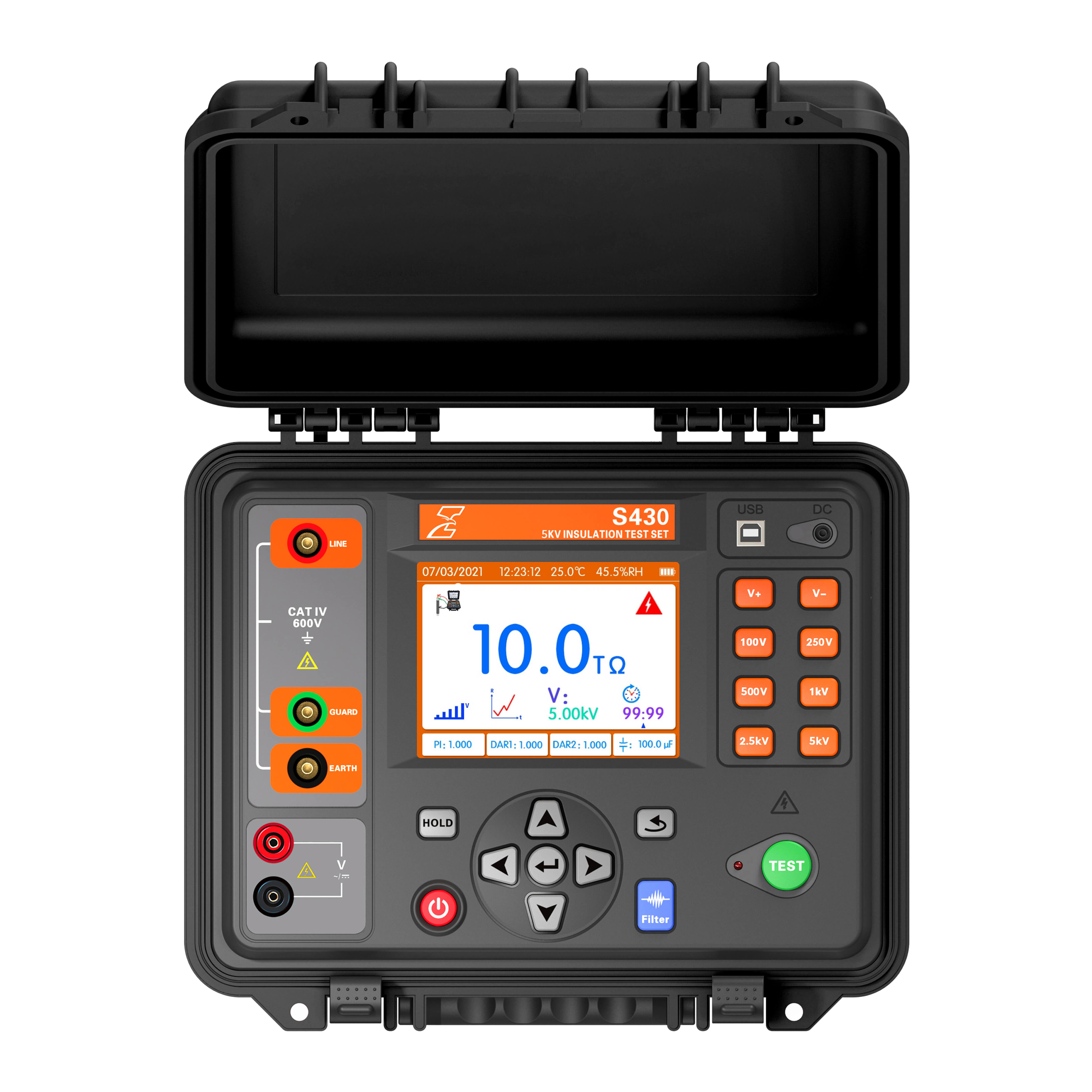
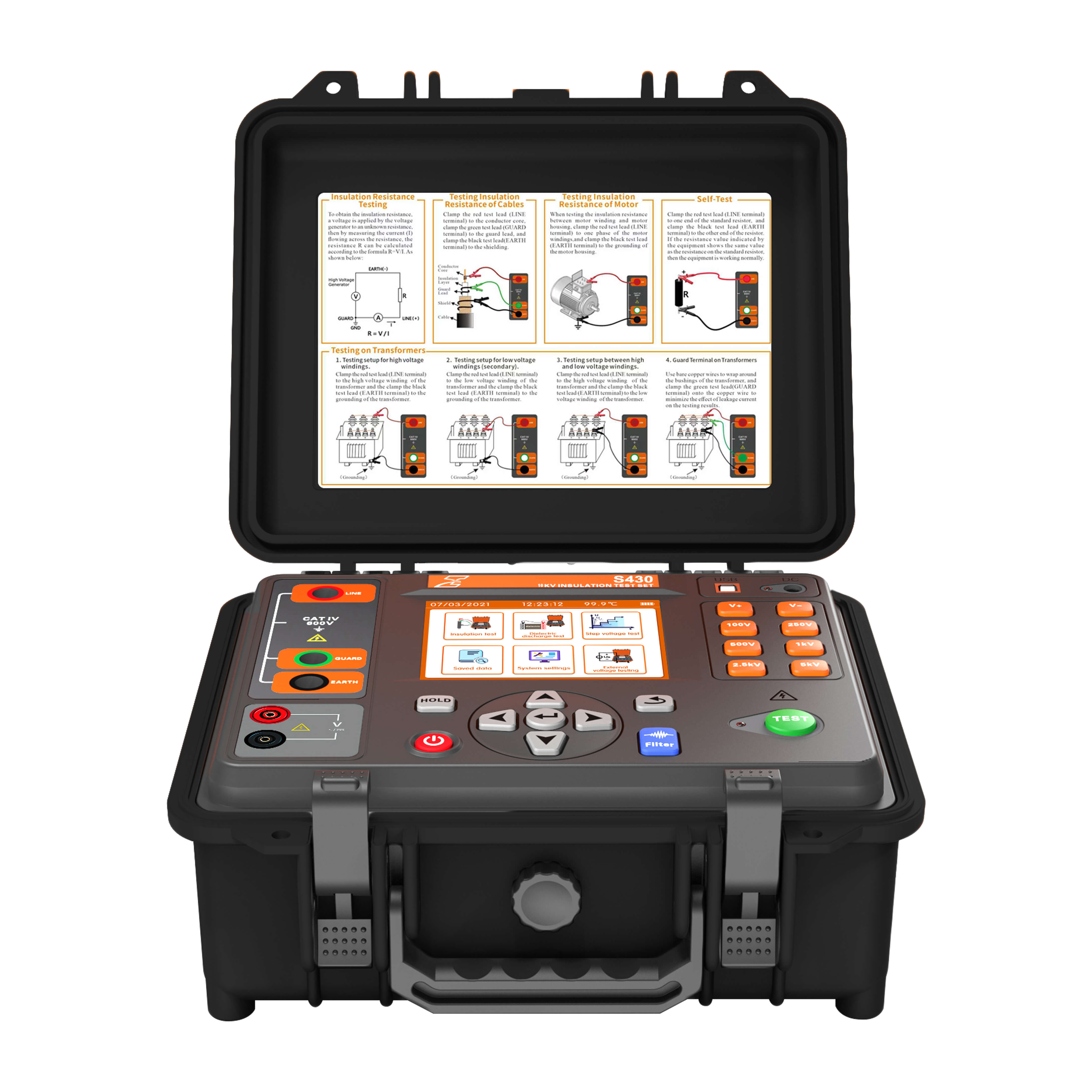
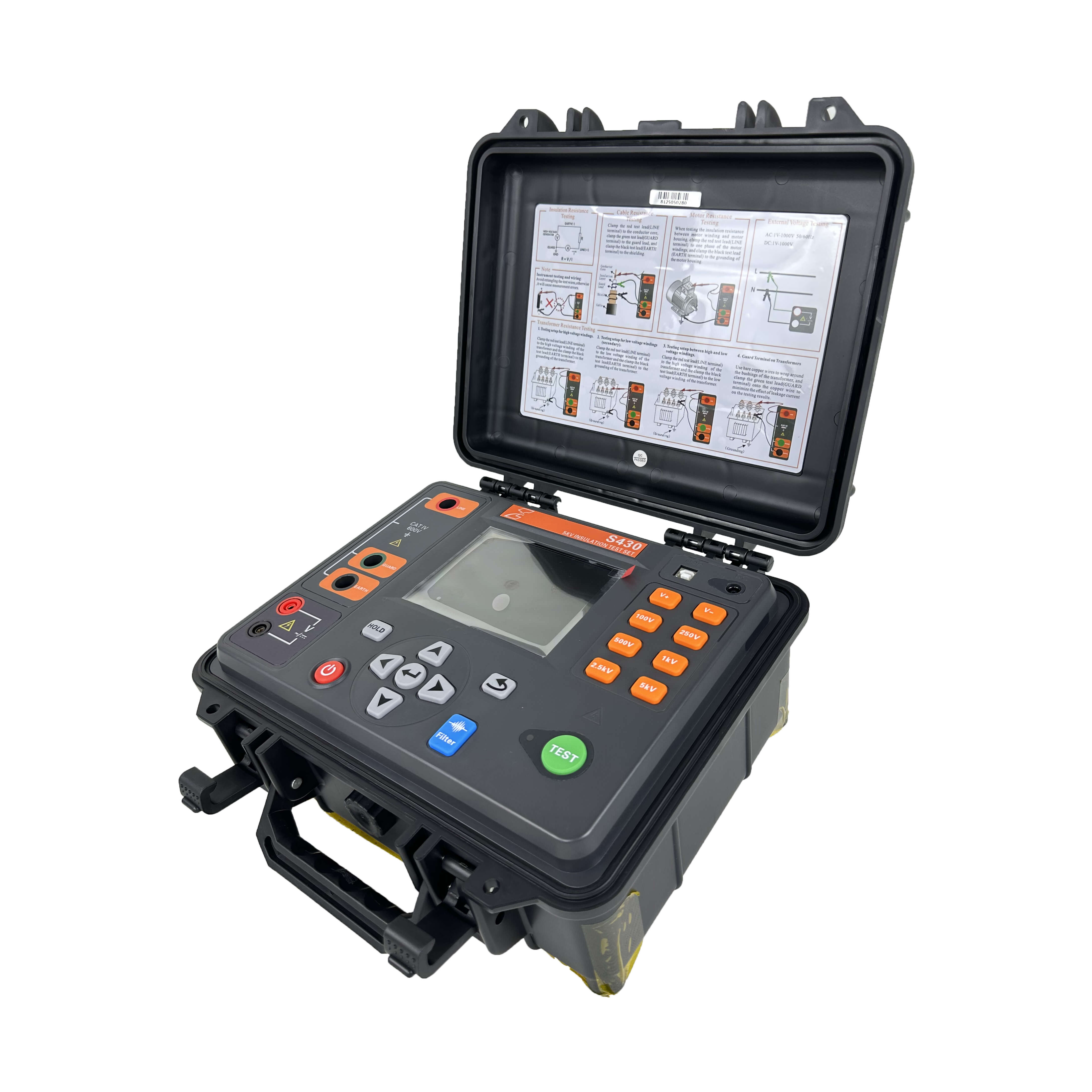
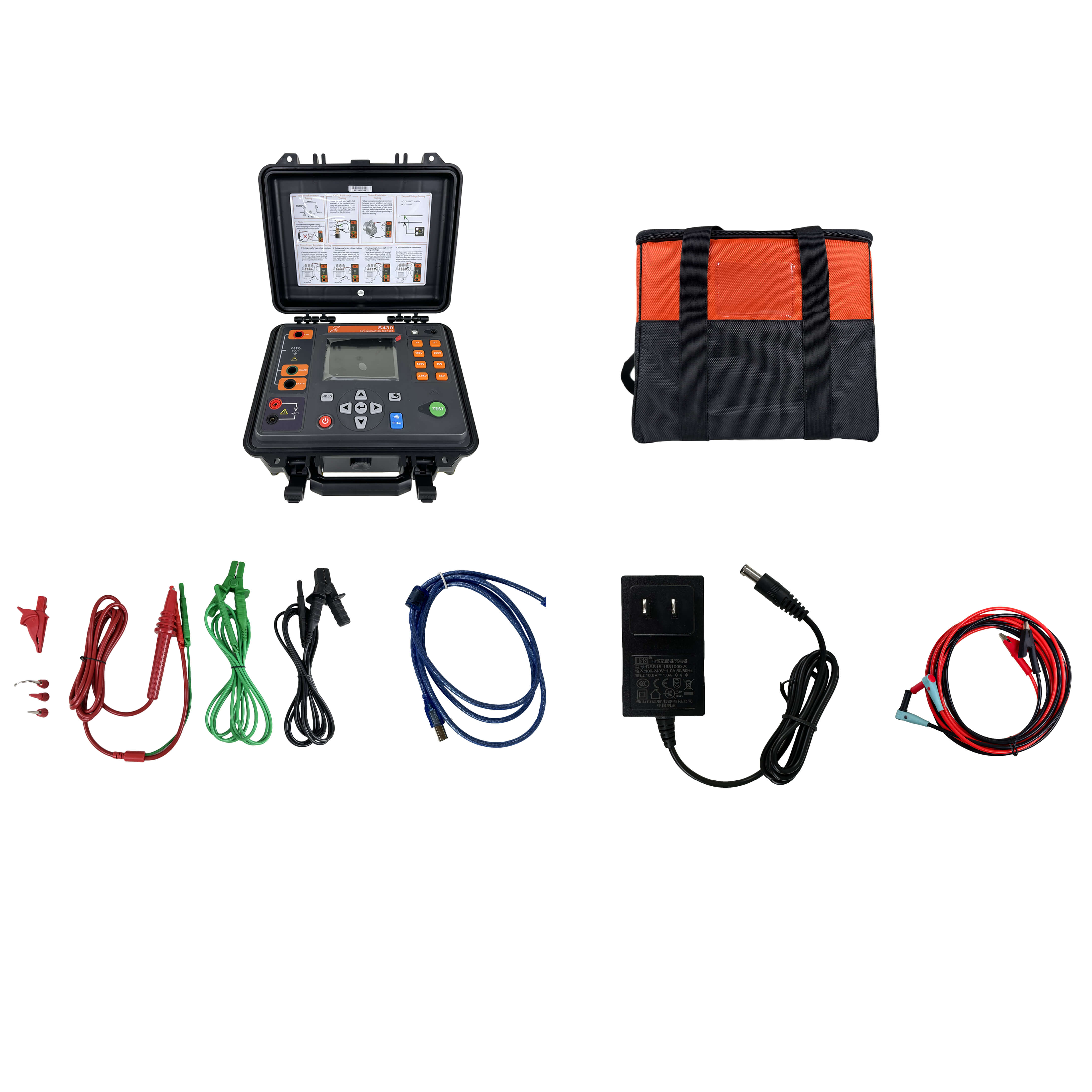
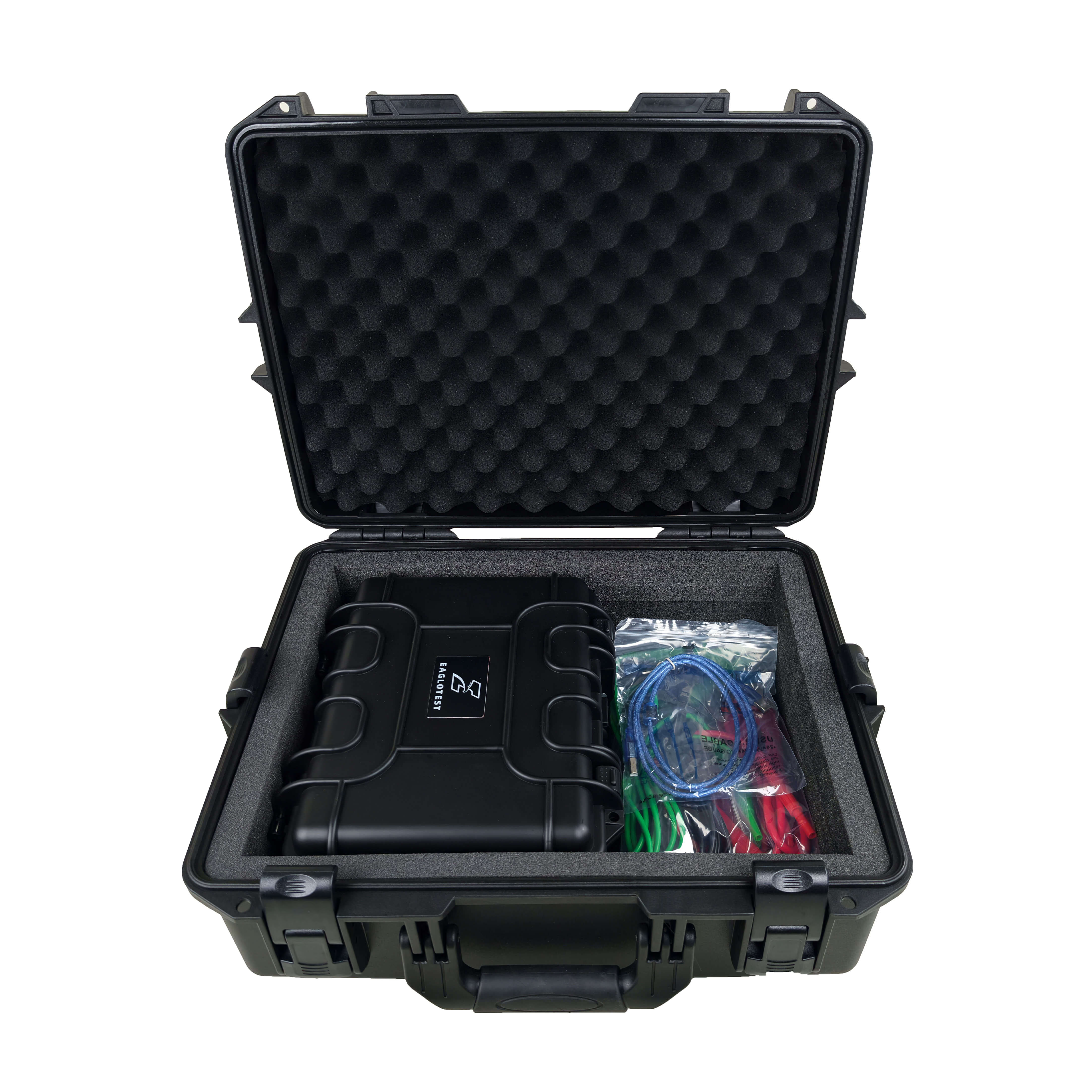

S430 5KV Insulation Test Set

  • Shock and weatherproof design

  • Dielectric Discharge test (DD) and Step voltage test (SV)

  • Noise filtering

  • Automatic discharge

  • Freely set both voltage and duration for each step

  • Capacitance and current readings

  • Data save & Hold

  • Measurement range: 0.01MΩ~10.00TΩ (5kV)

  • Resolution: 0.01MΩ

  • Short circuit current: 5mA

Product Description

The Digital 5kV Insulation Tester Model S430 is Eaglotest’s latest high-performance diagnostic tool, engineered for the rigorous maintenance of high-voltage electrical equipment. Built to deliver dependable precision even in electrically noisy substations, it provides comprehensive evaluations of insulation health through advanced automated diagnostics, including Polarization Index (PI), Dielectric Absorption Ratio (DAR), Dielectric Discharge (DD), and Step Voltage testing. The instrument boasts a massive capacity, measuring insulation resistance from 0.01 MΩ up to 10 Tera-ohms, alongside leakage current and capacitance, with highly flexible, adjustable test voltages ranging from 50V up to 5,000V.

Designed specifically for the practical needs of field engineers, the S430 is exceptionally compact and lightweight without sacrificing durability. It is housed in a rugged, industrial-grade carrying case that, when the lid is closed, provides heavy-duty shockproof and weatherproof protection. This robust design ensures the unit's internal components remain completely safeguarded against dust and moisture ingress during outdoor transport and demanding onsite use.


Technical FAQ
What is the difference between DAR and PI?
DAR and PI are timed insulation-resistance ratios used to assess how insulation behaves while the test voltage is applied. DAR normally compares the resistance measured at 60 seconds with the resistance measured at 30 seconds, while PI compares the resistance measured at 10 minutes with the resistance measured at 1 minute. DAR provides a faster indication, while PI evaluates insulation behaviour over a longer period.
Why does the insulation tester show a very high resistance or open-circuit result?
A very high resistance or open-circuit indication may mean that the insulation resistance is genuinely above the instrument’s measurement range. It can also be caused by a loose test lead, an internally disconnected test object or an incorrect connection. Confirm that the test leads are securely connected and perform a short-circuit check before repeating the measurement. Possible causes documented for the S430/S431 include poor lead connection, an extremely high-resistance object and an internally disconnected test object.
Why does the output voltage fail to reach the selected test voltage?
The output voltage may not rise to the selected level when the test object has very low resistance or excessive leakage current. A low battery can also prevent the instrument from supplying the required output. Testing equipment that has not been fully de-energized may create a voltage conflict. Stop the test, confirm that the circuit is isolated and discharged, check the battery and verify the test connections.
What is the purpose of the step-voltage test?
A step-voltage test applies progressively higher test voltages and records the insulation resistance at each level. It helps determine whether the insulation remains stable as electrical stress increases. A significant reduction in resistance at higher voltage may indicate contamination, moisture, insulation damage or another voltage-dependent weakness that may not be apparent during a single-voltage test. The S430/S431 step-voltage function applies voltage in increments and records insulation resistance at each step.
Must the test object be discharged after an insulation-resistance test?
Yes. Cables, transformers, motors and other capacitive test objects can retain hazardous electrical charge after the test voltage is removed. Keep the test leads connected until the instrument has completed its automatic discharge process and confirms that the remaining voltage is safe. Where required by the applicable safety procedure, verify the voltage independently before touching or disconnecting the test object.