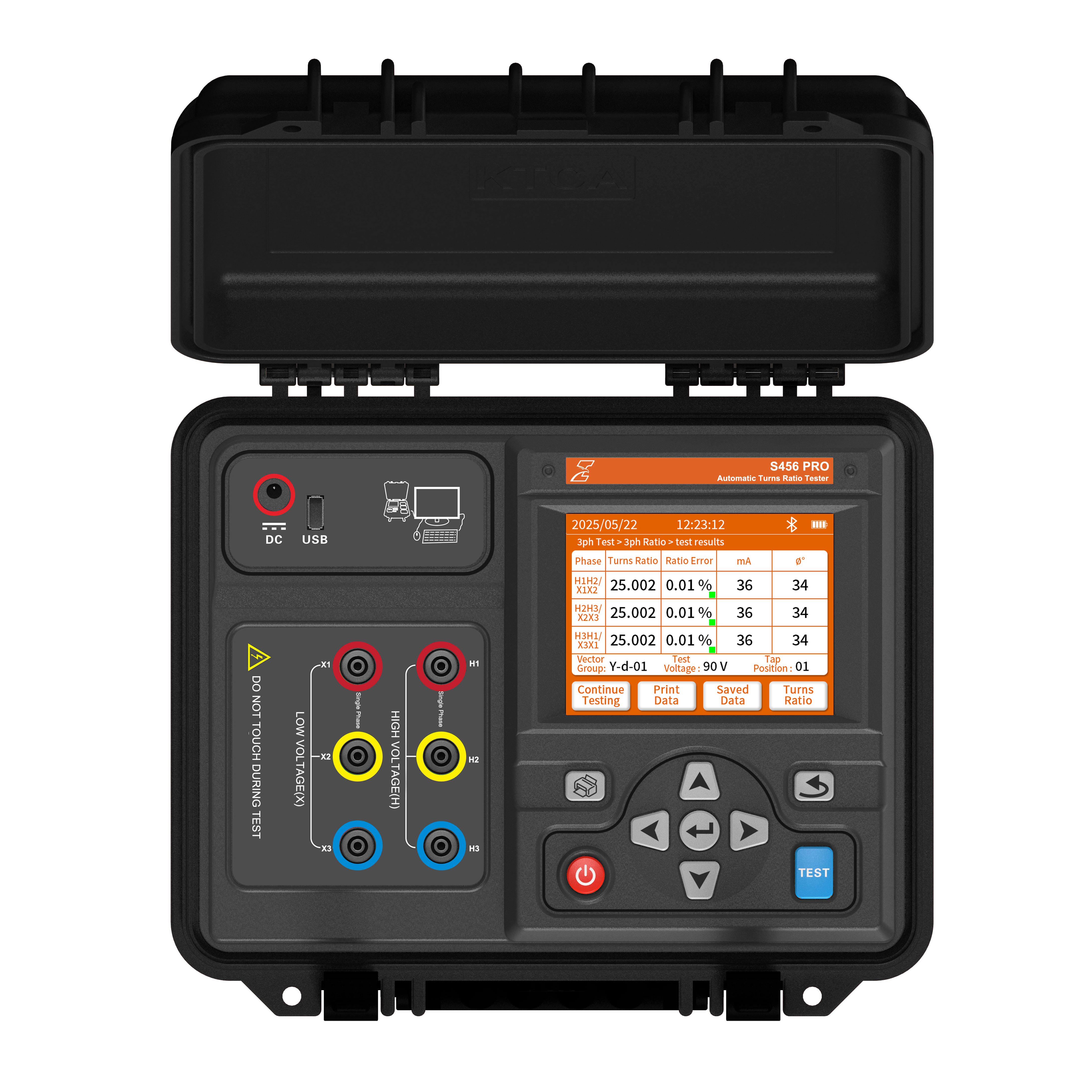

S456 PRO Turns Ratio Tester

  • Accurate and fast measurement (0.8000 to 10,000 ratio range, ±0.1% accuracy);

  • Resolution down to 0.0001

  • Auto vector recognition (4V to 90V AC test voltage);

  • Multi-parameter testing (Ratio, Excitation Current, Phase Angle & Tap Position);

  • 5.6-inch Color and Touch Screen;

  • App and Computer Software Control & Export Report;

  • 500 records internal memory with auto save and full circuit protection;


Product Description

Measuring the turns ratio, ratio error, excitation current, and phase angle deviation of power transformers, distribution units, Voltage Transformers (VT), and Current Transformers (CT) is essential for verifying winding manufacturing tolerances, identifying inter-turn short circuits, evaluating tap-changer contact integrity, and preventing insulation breakdown or equipment damage prior to commissioning.


  • The S456 PRO Automatic Three-Phase Transformer Turns Ratio Tester automatically measures turns ratio (0.8000 to 10,000), ratio error (±(0.1% rdg + 3 dgt) with 0.0001 resolution), excitation current (0.01 mA to 1000 mA with 0.01 mA resolution), phase angle deviation (0.0° to 360.0° with 0.1° resolution), and vector group configuration in a single test sweep.


  • Simultaneous Three-Phase Excitation: Features a three-phase sinusoidal inverter output with a maximum test voltage of 90 V AC (50 Hz) to excite and measure all three phases simultaneously. The stable internal test source combined with synchronous three-phase measurement helps mitigate the impact of test voltage fluctuations and site interference, enhancing the stability of phase angle and turns ratio measurements while significantly improving field testing efficiency.

  • Blind Test Vector Group Identification: Automatically identifies unknown transformer vector groups and clock phase angles (4V to 90V AC) without requiring prior nameplate data.

  • Multi-Asset Compatibility: Fully compatible with three-phase transformers, single-phase units, Zigzag (Z-type) distribution transformers, Voltage Transformers (VT), and Current Transformers (CT).

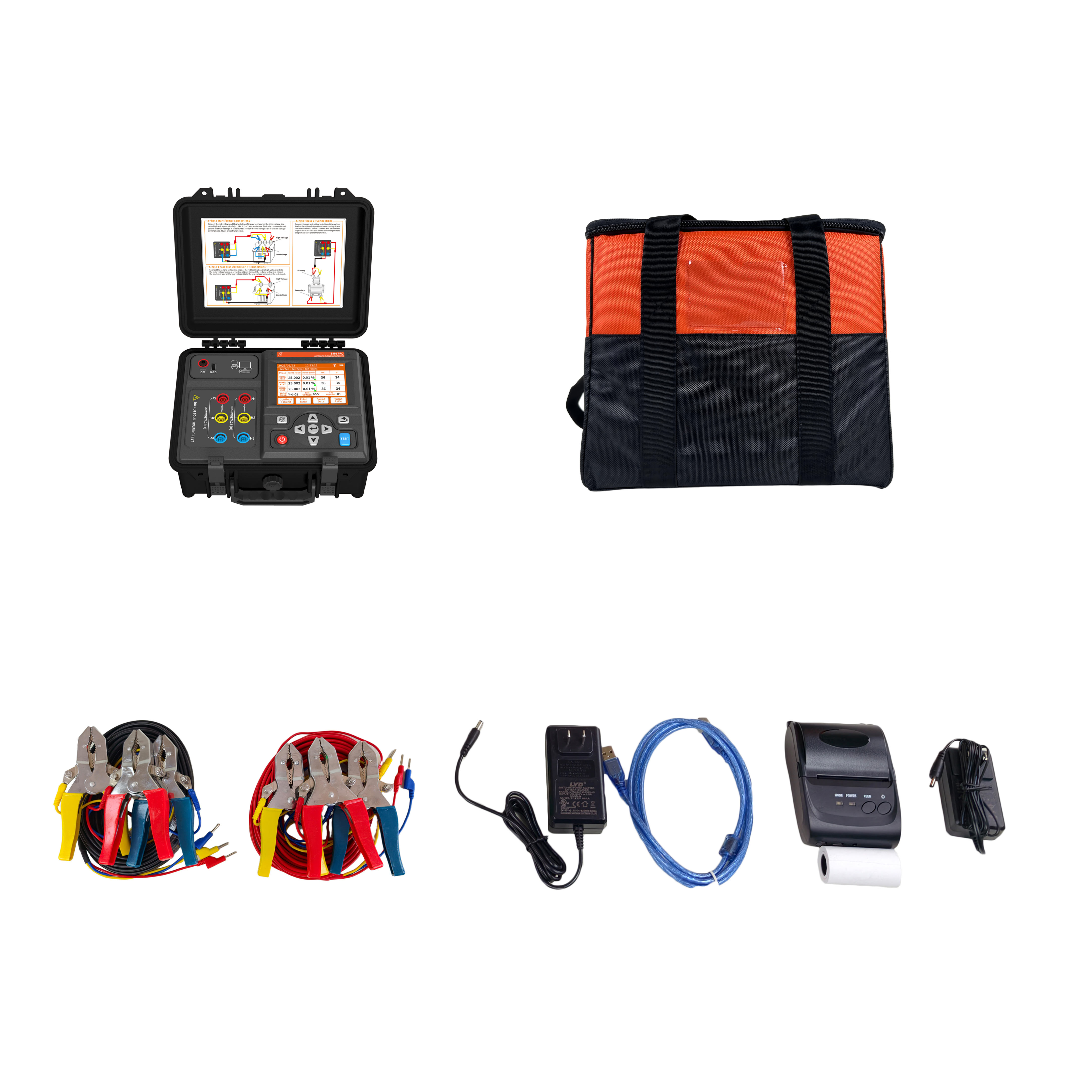
  • Rugged Enclosure & Wireless Workflow: Features an IP54-rated heavy-duty casing weighing 3.5 kg, an internal 12.6V 5200mAh rechargeable lithium battery, 10 m test leads with 50 A heavy-duty clamps, a 5.6-inch colour touchscreen, Bluetooth mobile app control, and USB PC reporting software.

  • Scope of Application: Engineered for Factory Acceptance Testing (FAT), site commissioning, routine predictive maintenance, overhauls, and fault investigations.


Technical FAQ
What is the difference between Normal Test and Blind Test modes on an automatic three-phase transformer turns ratio tester?
On an automatic three-phase transformer turns ratio tester, Normal Test mode requires entering the known vector group (e.g. Dyn11 or Ynd1) and rated high/low voltages (0.8000 to 10,000 ratio range) prior to test execution. In contrast, Blind Test mode utilizes automatic vector group recognition. The instrument applies a controlled three-phase inverter test voltage (4V to 90V AC) to automatically detect the transformer's clock phase angle, vector connection, and turns ratio without requiring prior nameplate data—ideal for field testing unlabelled or legacy substation equipment.
Is a neutral connection required for three-phase testing?
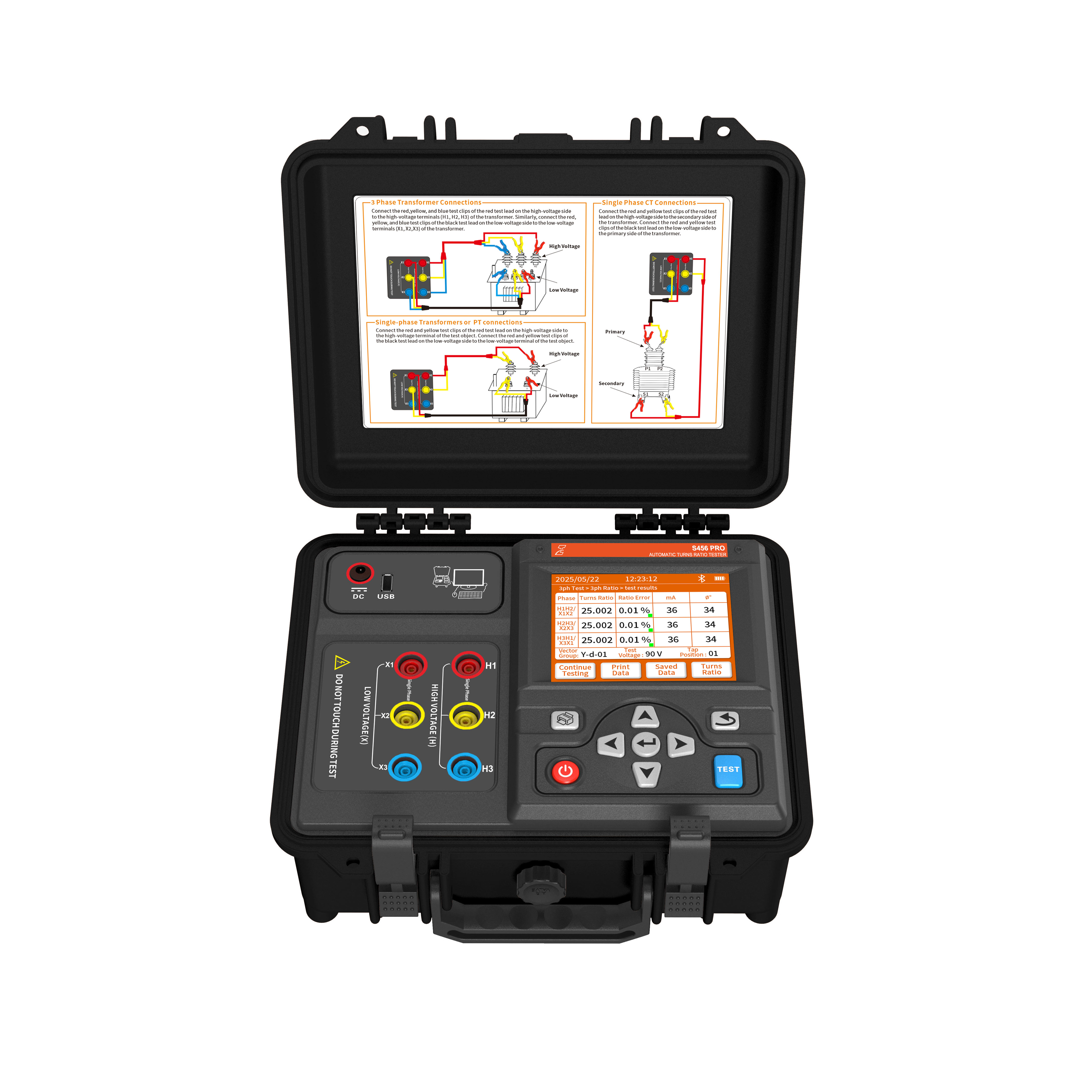
No neutral connection is required. The device has no neutral terminal. For three-phase transformer testing, operators connect the HV test lead (red, yellow, blue clamps) directly to the high-voltage phase terminals (H1, H2, H3) and the LV test lead (red, yellow, blue clamps) to the low-voltage phase terminals (X1, X2, X3) using 10 m sheathed test leads with 50 A heavy-duty clamps. The internal microprocessor automatically calculates phase-to-phase and phase-to-neutral vector relationships based on the selected or detected vector group configuration.
What are the benefits of simultaneous three-phase excitation?
An advanced automatic three-phase transformer turns ratio tester features a three-phase sinusoidal inverter output with a maximum test voltage of 90 V AC (50 Hz) to excite and measure all three phases simultaneously. The stable internal test source combined with synchronous three-phase measurement helps mitigate the impact of test voltage fluctuations and site interference, enhancing the stability of phase angle and turns ratio measurements while significantly improving field testing efficiency. Furthermore, by capturing turns ratio (0.8000 to 10,000, best accuracy ±(0.1% rdg + 3 dgt)), excitation current (0.01 mA to 1000 mA with 0.01 mA resolution), phase angle deviation (0.0° to 360.0° with 0.1° resolution), and tap position (1 to 197 positions) in a single sweep, field engineers can perform comprehensive 4-in-1 diagnostics to instantly distinguish tap changer setting errors from internal winding defects or inter-turn short circuits.
How does phase angle deviation measurement improve diagnostics in a transformer ratio test set?
While basic meters measure voltage ratio alone, an advanced digital TTR tester with phase angle measurement evaluates the precise angular difference (0.0° to 360.0°, resolution 0.1°, accuracy ±0.5°) between the primary applied voltage and secondary induced voltage. Significant phase angle deviations highlight core magnetization imbalance, phase sequence reversal, severe winding displacement, or incorrect vector group wiring, providing comprehensive diagnostic reference before re-energising transformer assets.
What are the exact test lead connection procedures for single-phase transformers, PTs, and Current Transformers (CTs)?
When testing single-phase transformers or Potential Transformers (PT), clamp the HV test lead's red and yellow clamps to the high-voltage side of the specimen, and the LV test lead's red and yellow clamps to the low-voltage side. When testing single-phase Current Transformers (CT), clamp the instrument's HV test lead (red and yellow clamps) to the secondary side (S1, S2) of the CT, and the LV test lead (red and yellow clamps) to the primary side (P1, P2). In CT mode, selectable test voltages are restricted to 4V or 10V AC to ensure complete measurement integrity and compliance with IEC 61010-1 safety regulations.