Introduction
The purpose of an Earthing in an electrical system is that it prevents the system from being overloaded from high potentials, which can be caused by, lightning strikes or voltage spikes. It provides a path for conducting the surges safely to the earth, preventing the system voltage to exceed the rated voltage level. Therefore, the resistance of the earthing needs to be very low in order for the fault current to pass through.
Resistance to earth can vary with changes in climate and temperature. Such changes can be considerable. An earthing that was good (low-resistance) when installed may not remain the same over a certain period of time, in order to be sure, periodic tests must be conducted.
Another crucial factor that can contribute to the resistance of a system earthing is the soil resistivity. Before providing the earthing to a system, it is essential to determine the resistance of that particular area or the type of soil the earth electrode will be driven in, because whether the soil is largely clay or very sandy, for example, can affect the earth resistivity greatly.
Problem
Determine the resistance of an installed electrode
Determine the soil resistivity of the area of earthing.
Solution
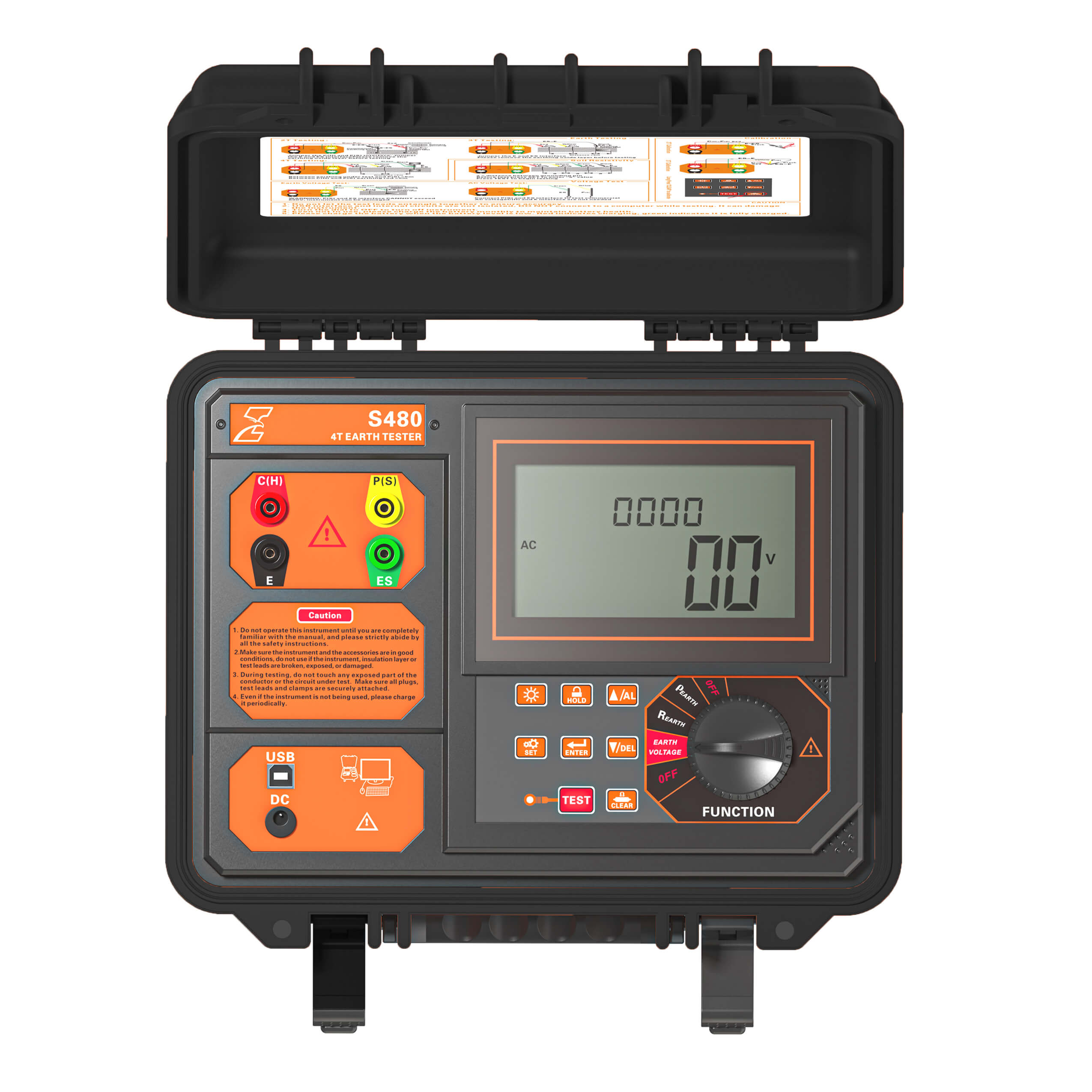
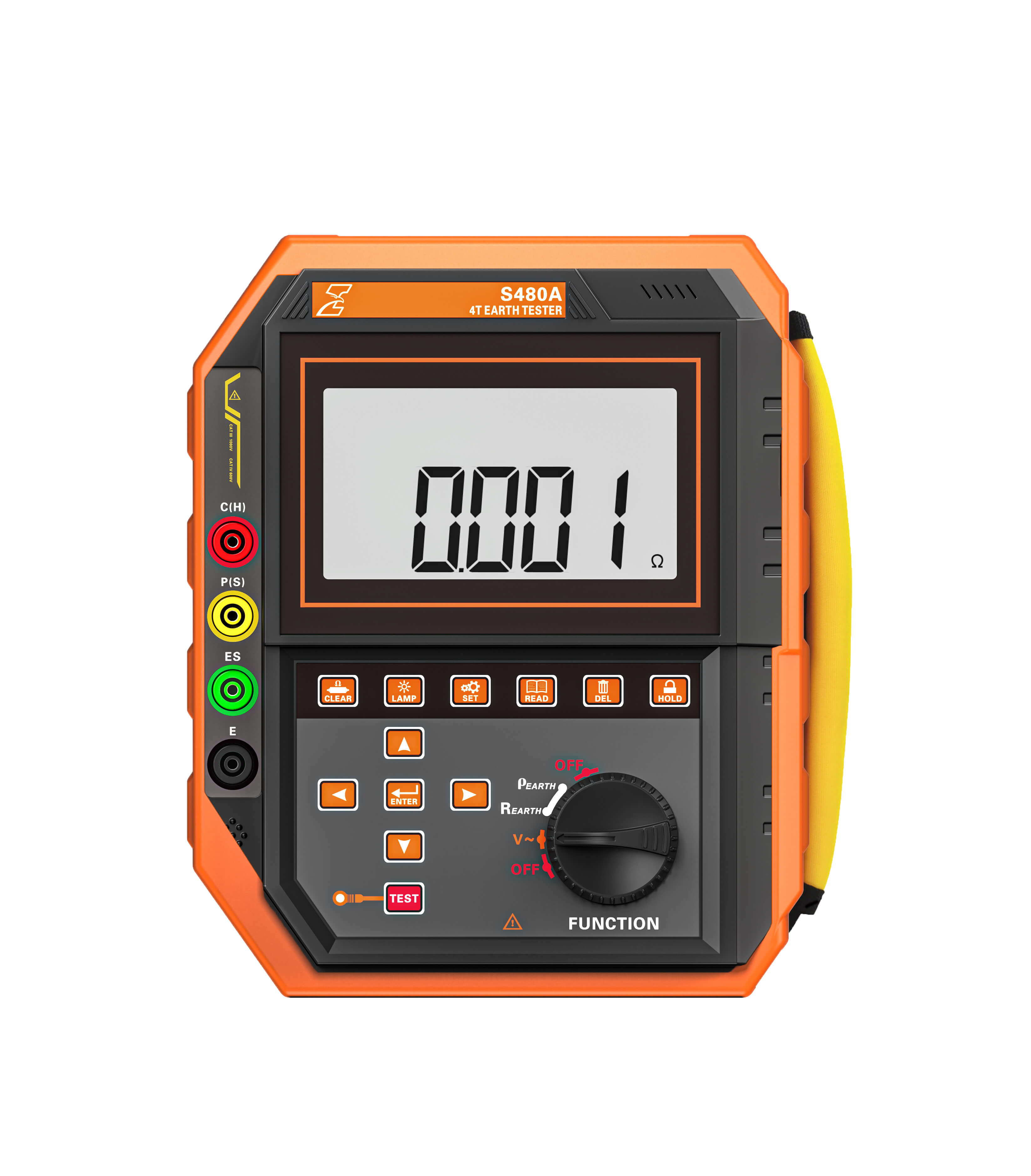
The S480/S480A is an easy-to-use instrument that enables users to quickly measure the resistance of the earthing and the soil resistivity. Using the 4-terminal method, it can minimize the effect of line and contact resistance.
Difficulties
In situations where the resistance is abnormally high while testing, try pouring water around the electrodes to increase the contact surface between the electrodes and the soil, this could lower the resistance.
Benefits
- Resolution 0.001 Ω and 0.01 Ω
- 2% accuracy
- 4 Terminal testing
- Test range 0.000 Ω ~ 200.0k Ω
- Earth and soil resistivity testing
- Fast Fourier Transform (FFT) and Automatic Frequency Control (AFC)
- Anti-interference